
The evolving distribution networks
Contributor: James Yu
Most responsible governments have committed to a low carbon economy. The UK government has set out a clear ambition to take on the leadership in this international transition. A low carbon electricity network is critical to enable and to realise such a commitment. Unlike a conventional network where centralised generation is to supply all the electricity demands, more and more distribution connected resources (most of them are in the form of renewables) are playing an increasing active role in electricity supply security and reliability. From engineering perspective, the phenomenon can be reflected as the controllable and bi-directional power flow between transmission networks and distribution networks; from the customer perspective, customer can also take on multiple roles simultaneously be a generator or active demand responses party.
The GB Energy System Operator has already made a clear commitment that by 2025, it will have transformed the operation of Great Britain’s electricity system and put in place the innovative systems, products and services to ensure that the network is ready to handle 100% zero carbon. [1]
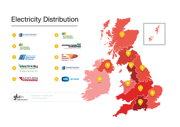
The majority of existing electricity networks were built in 1950s and 1960s, therefore a significant investment is required to renovate the network while expanding it at the same time to meet the electricity demand growth. GB networks operators have collectively been set to spend over £26billion between 2015 and 2023 to ensure GB grid can provide adequate available capacity to allow secure energy transfer to the customers, in additional to the £2billion per annum investment planned for transmission sectors and the bespoke Strategic Wide Works such as the Shetland HVDC Link, estimated about £800m. Distribution Network Operator (DNO) serves as the direct interface and takes on active coordinating role between all market participants, facilitating the markets and services in a neutral and non-discriminatory manner.
This can be achieved by extending the current role of DNOs to that of Distribution System Operators (DSOs). An effective DSO model will reduce system balancing costs, whilst enabling the flexible networks necessary to facilitate customer’s use of low carbon technologies. [2]
Innovation and sustainability have to play the critical role in a post-Pandemic economy. the distribution network is evolved to have more visibility and more controllability than ever before. Decentralisation, Decarbonisation and Digitalisation are the main themes of the distribution network development. Commercial innovations and the engineering advancement alike are required to enable a smarter distribution networks to meet the future requirements of our customers. The technology advancement of power electronics and its commercial availability are the catalyst of this transformation.
[1] https://www.nationalgrideso.com/news/zero-carbon-operation-great-britains-electricity-system-2025
The enabling function of power electronics
Power electronics will play a key role in power systems of the future with multiple functionalities. An important area of application is identified in the distribution networks for larger uptake of low carbon technologies. Moreover with the uncertain nature associated with renewable resources (such as solar and wind) and the distributed renewable resources an enhanced co-ordination and management is required. The engineering challenges associated with integrating the unprecedented level of distributed renewable generations can include but not limited to:
- The unpredictable power flow from the embedded generation;
- Imbalance of energy demand between the 3-phase of AC supply;
- Wide voltage angle can prevent the connection between key circuits;
- Voltage control at both transmission and distribution level;
- Power quality
Power electronic device has been conventionally deployed at the renewable sector to fulfil the requirements set out in the Grid Code or Connection Codes, such as Fault Ride Through; Reactive power control (and the voltage control) on the connected busbar. With the help of power electronics solutions, power flow can be controlled in a wide range of conditions, and make it possible to implement widely.
The requirement to maintain a secure, reliable and economical distribution network has seen the increasing activities in both the engineering developments, such as
- The power electronic material (silicon carbide power electronics),
- Hardware design (e.g. new topology of converter; Solid State Transformer);
and the commercial innovation, such as:
- The planning and ownership of Statcom at Grid side
- Integrated function of synchronous condenser and Statcom to provide frequency support
[2] The customers are potentially paying distributed renewable generators over £1billion forecasted constraint costs within the coming two years (by April, 2022): https://data.nationalgrideso.com/balancing/bsuos-monthly-forecast/r/bsuos_forecast_for_summer_2020_–_including_new_services_–_forecast
Challenges with Power Electronic Devices
In additional to the ongoing engineering and commercial innovation in the power electronic sectors, there are still challenges prevailed over their widespread application in the power systems domain. The challenges associated with proliferation of power electronic devices in the distribution grids can include but not limited to:
- Converter topology suitable for different voltage levels in the distribution grids
- The selection of passive (inductors, capacitors and resistors) and power electronic components, with respect to size and power density.
- Selection of suitable power electronic materials based on application and voltage level (Silicon Carbide, Gallium Nitride etc)
- Reliability of the power electronic and its associated components
- Cost of power electronic devices and associated control systems
- Efficiency and power losses related to power electronic devices.
Existing Project (Pictures and reference)
CIGRE is an established international organisation and taking on the expectations to coordinate and standardise the relevant activities in this sector. Based on the previous efforts from working groups of both C6 (Distribution Systems and Dispersed Generation) and B4 (HVDC and Power Electronics). The newly established collaborative working group: C6.B4.37: Medium Voltage Direct Current has been set up to champion the efforts at international level.
A power electronic-based network upgrade can solve the issues associated with the traditional MV systems such as active control of the active and reactive power, independent reactive power compensation, harmonics and unbalance on the on the AC grids. To this end, a few existing examples are presented here
Example 1: ANGLE DC Project
Angle-DC is a smart and flexible method for reinforcing MV distribution networks, operated by Scottish Power Energy Networks. Angle-DC provides controllable power electronic based flexible connection that facilitates enhanced bi- directional power flow between two sections of the network, Isle of Anglesey and North Wales. The project aims to convert the existing 33kV Alternating Current (AC) assets to DC operation and will trial the first flexible MVDC link in the GB distribution system. Moreover, the project will provide learning to bridge the gap between transmission network and low voltage distribution DC technologies. It is expected that Angle -DC will bring a total saving of £69.2m by 2030 and £396.0m by 2050.
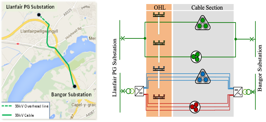
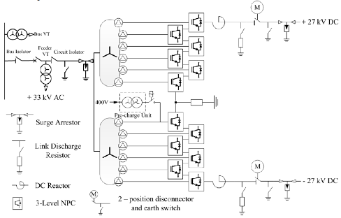
Figure 1 Single line circuit of the Angle-DC link with MVDC topology [1].
Example 2: LV Engine
LV Engine will trial the application of power electronic based smart transformers (STs) to facilitate the connection of Low Carbon technologies (LCTs). A ST is a power electronic device that provides multiple functionalities over and above standard voltage conversion of conventional transformers. SP Energy networks run the project and aims to demonstrate a low voltage Direct Current (DC) connection for LCTs. It is expected that LV Engine will bring a potential saving of £62m by 2030 and £528m by 2050.
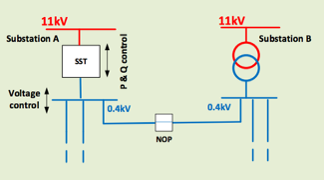
Figure 2 Connection Scheme of SST to LV network [2]
Example 3: UK Network Equilibrium project
The project aims to install a back-to-back power electronic convertor (AC-DC-AC) which will allow power transfers across two different 33kV networks, called Flexible Power Link (FPL). The FPL will allow controlled transfers of both real and reactive power flows between the two networks. Western Power Distribution (WPD) as part of their “Network Equilibrium” project runs this activity. It is estimated that deploying such flexible power links across the UK could release 1.5 GW of capacity by 2050.
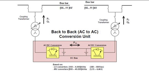
Figure 3 Back-to-back Flexible power link connection between two grids [3].
Example 4, Indonesia
Coupling of an industrial grid including own generation, highly unbalanced and distorted load (arc furnace) with a public grid. There is a surplus of generated energy in the industrial grid, but both grids cannot directly be interconnected. A back-to-back converter with sufficient rating towards the industrial grid to compensate the unbalance and lower order harmonics interconnects both grids. It reduces the unbalance load on the industrial grid power generators, reduces the harmonics in the industrial grid and enables four-quadrant power transfer between both grids.
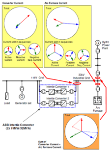
Figure 4 Back-to-back Intertie connection between two industrial Grids [4].
Example 5, China – Wenchang Project
An MVDC system has been provided for CNOOC as part of the Wenchang platform submarine cable repair project. This was provided by the specialist power electronic equipment manufacturing RXPE on a turn-key basis.
The Wengchang project was started in 2010 as a result of customer negotiations and participation with the RXPE business, product development and engineering departments to help address the urgent loss of supply security problem. The MVDC was configured as a symmetrical bipole with a rating of 8 MVA / ±15kV, such that the positive and negative poles are identical and each pole can work independently of the other to provide security of supply to the remote platforms. The projects aims to convert a faulted 35 kV AC line to 3 MW DC line with voltage-source converter (VSC) topology as discussed in [5].
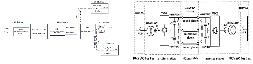
Figure 6 8 MVA / ±15kV Wenchang MVDC project (a) Schematic diagram; (b) AC to DC operation schematic [5-6]
Example 6 Kylmäkoski, Finland
Pilot implementation of a point-to-point type of LVDC system implemented in co-operation with Elenia Oy (DNO) and ABB Oy Drives. Rectifier is a standard ACS800-11 module where only the bidirectional input power stage is used. The DC-voltage is boosted from normal 570VDC to 750VDC to minimize the DC-current and to maximize the available energy in DC-capacitor bank. The cabinet of the inverter consists of a 150 kVA converter module, an output transformer and an additional DC-capacitor bank as energy storage. The output transformer is a normal dry Dyn distribution transformer with a static shield and 460/400V transformer ratio.
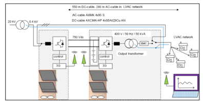
Figure 7 Schematics of the LVDC pilot setup [7].
References
[1] J. Yu, A. Moon ,K. Smith, and N. MacLeod, “Developments in the Angle-DC project; conversion of a medium voltage AC cable and overhead line circuit to DC,” CIGRE B4, Paris Session, 2018.
[2] Electricity NIC submission: SP Energy Networks– LV Engine, Nov 2017
[3]J. Berry, “Network equilibrium. Balancing generation and demand. Project progress report Dec 2015 – May 2016,” 17 June 2016. [Online].
[4] ABB, “PRS SFC INCO EN,” 4 August 2006. [Online]. Available: https://library.e.abb.com/public/d20bc6e606717f9bc12576c40043ea95/PCS%206000%20STATCOM_INCO_EN.pdf.
[5] Y. Liu, X. Cao and M. Fu, “The Upgrading Renovation of an Existing XLPE Cable Circuit by Conversion of AC Line to DC Operation,” in IEEE Transactions on Power Delivery, vol. 32, no. 3, pp. 1321-1328, June 2017.
[6] G. Bathurst, G. Hwang and L. Tejwani, “MVDC – The New Technology for Distribution Networks,” 11th IET International Conference on AC and DC Power Transmission, Birmingham, 2015, pp. 1-5.
[7] T. Hakala, T. Lähdeaho and P. Järventausta, “Low-Voltage DC Distribution—Utilization Potential in a Large Distribution Network Company,” in IEEE Transactions on Power Delivery, vol. 30, no. 4, pp. 1694-1701, Aug. 2015.